• Skip to primary navigation
  • Skip to main content
  • Skip to primary sidebar

PMS Instrument Company

  • Home
  • About Us
    • Biography of Henry Dixon
    • Biography of John Joly
    • Biography of Per Scholander
    • History of PMS Instrument – Joe Zaerr
    • History of the Scholander Pressure Chamber
  • Products
    • Model 600
    • Model 600D
    • Model 600-EXP Super Chamber
    • Model 615
    • Model 615D
    • Model 670
    • Model 1000
    • Model 1505D
    • Model 1505D-EXP
    • Model 1515D
    • Pump-Up Chamber
  • Agriculture
    • Using a Pressure Chamber with wine grapes
    • Using a Pressure Chamber with Almond
    • Using a Pressure Chamber with Walnuts
    • Using a Pressure Chamber with Prunes
    • Stress levels, crop tables and information
  • Maintenance
  • Resources
    • References
  • How to Order
  • Contact Us
  • Show Search
Hide Search
You are here: Home / Instrument Maintenance / Digital Gauge Battery Replacement

Digital Gauge Battery Replacement

Warning!Important Safety Information
« Click Here

If your instrument is fitted with a digital pressure gauge, this tutorial will demonstrate how to replace the two (2) AA batteries that supply power to the gauge. This tutorial applies to the following Instruments:


Model 600D, Model 615D, Model 1505D, Model 1515D, Model 1505D-EXP, and Model 600D-EXP.


You will need: 1 Flat Head Screwdriver, 1 Small Flat Head screwdriver, 2 AA Batteries.

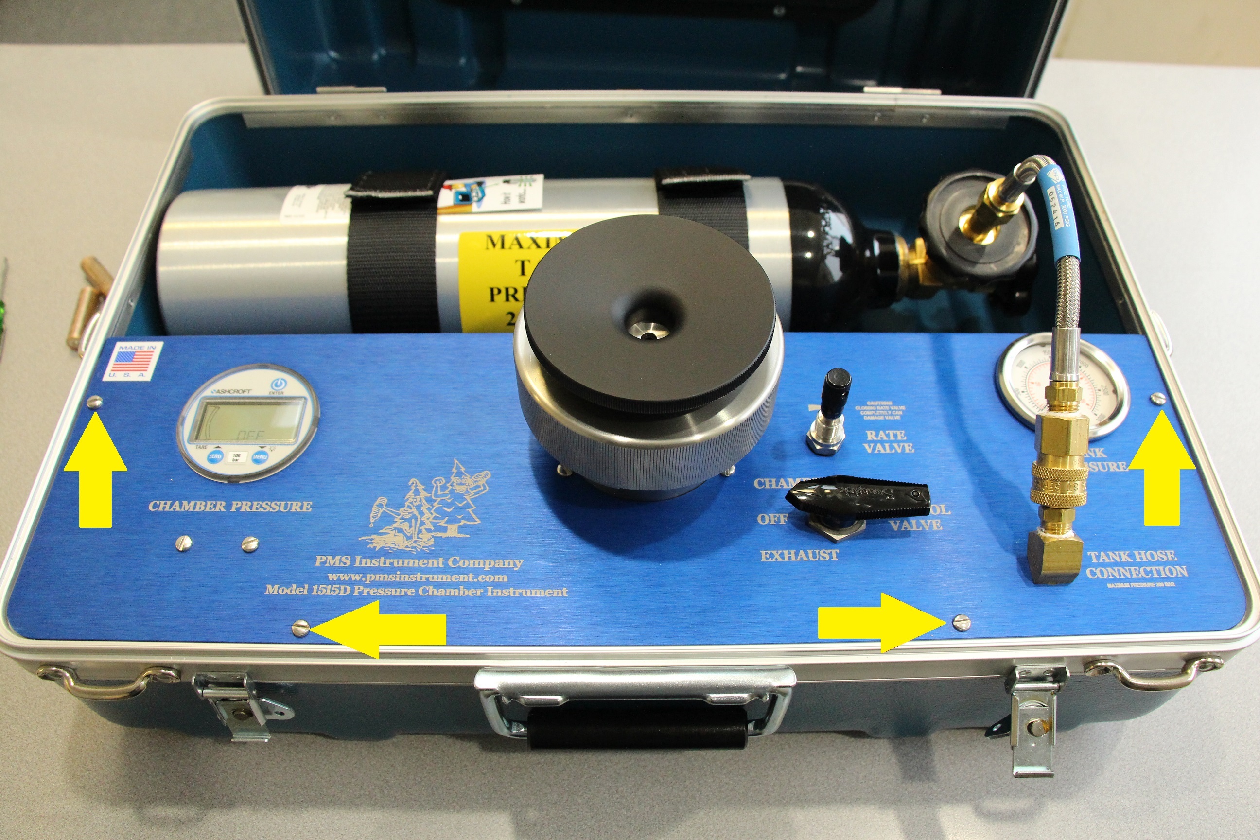
Step 1: Remove the 4 screws holding the Instrument Panel in place. These screws are located on the edge of the instrument panel as seen below.


Step 2: Remove the Instrument Panel and turn it over to expose the back side of the instrument panel.

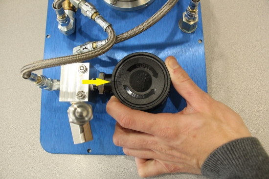
Step 3: Grasp the back of the gauge and turn Counter-Clockwise to the “un-locked” position. If the back has not been removed for awhile, it may be difficult to break the seal of the o-ring.


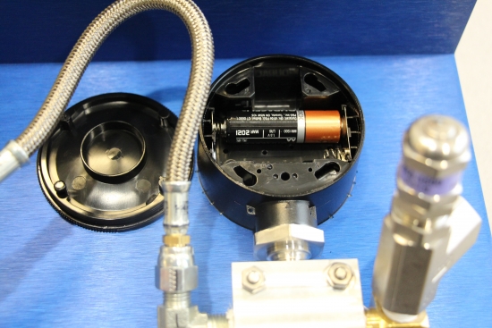
Step 4: Remove the two AA batteries and replace, making sure to place the batteries with the correct polarity.

Step 5: Replace the back of the gauge panel and turn Clock-Wise to lock it into position. This may require a small amount of force applied downwards in order to seat the o-ring before turning Clock-Wise.

Step 6: Place the Instrument Panel back onto the case and align the holes for the screws.

Step 7: Place all 4 screws into the holes and turn them a few times by hand to ensure they are not cross-threaded. Screw them down to hand tight with the screwdriver. DO NOT OVER TIGHTEN.

If you have any questions or issues replacing the batteries, please give us a call or email and we will be happy to assist you.


PMS INSTRUMENT CO.
541-704-2299
info@pmsinstrument.com

Primary Sidebar

Maintenance Topics:

  • Instrument Maintenance
    • Adjusting the “Brass” – Control Valve
    • Adjusting the “Stainless Steel” – Control Valve
    • Cleaning the O-Ring on the lid
    • Cleaning the Safety Valve
    • Digital Gauge Battery Replacement
    • Instrument Quick-Connect Couplers
    • Maintenance for Compression Gland Lid
    • Maintenance for the Portable Tank
    • Testing the instruments safety features
  • Maintenance for the Pump-Up Chamber
    • Pump-Up Chamber is leaking
    • Pump-Up Chamber will not increase in pressure
    • Basic Maintenance of Pump-Up Chamber
    • Changing O-ring on Lid of Pump-Up Chamber
    • Changing Piston Cup on Pump-Up Chamber
    • Lubricating the piston of the Pump-Up Chamber

Copyright © 2025 PMS Instrument Company | LOGIN