 Important Safety Information
« Click Here
Your instrument might be fitted with a Brass or Stainless Steel Control Valve. The procedure to make this adjustment is similar but requires a different tool. Look at the Control Valve on your instrument. If it is made of Brass – use this tutorial if it is made of Stainless Steel – click here for the Stainless Steel tutorial.
The Control Valve is the valve that directs the flow of nitrogen from CHAMBER / OFF / EXHAUST. This valve will require periodic adjustment. If a leak is in the control valve, the symptoms are generally a continual flow of gas into the chamber even while the instrument is in the OFF position. To correct this, follow the instructions below:
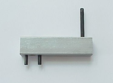
You will need only one tool for this- a Valve Adjustment Tool. This tool was provided with your instrument when you originally purchased it. If you have misplaced it you can purchase another one from PMS Instrument.
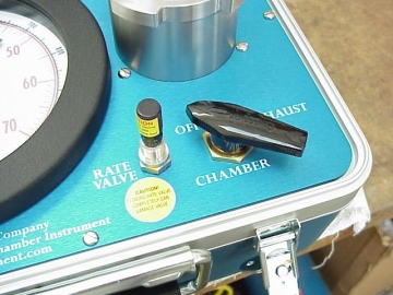
1. Connect instrument to a supply tank. Remove lid of chamber and turn valve to the “OFF” position. Listen for gas leak. (Make sure that you are in a quiet environment that allows you to detect when the gas hiss stops).
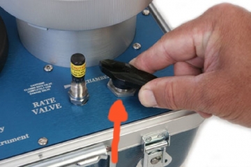
2. Use the allen key end of the valve adjustment tool to loosen the set screw in black handle of the control valve. Lift the handle straight up to remove.
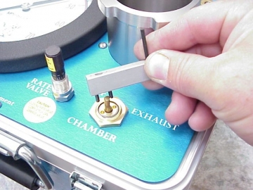
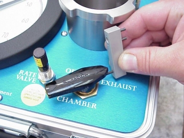
3. Using the two prong end of the valve adjustment tool, insert prongs into packing gland over valve stem.
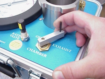
4. Rotate wrench clockwise until the gas leak can no longer be heard.
Caution:
Do not over tighten the valve packing, as permanent damage will result. Remove wrench, reinstall the black handle so that it points to the “off†position, and tighten the set screw in the handle. Over tightening can additionally make the valve too tight to function normally.
Note: If the instrument is used over a wide range of temperatures, some adjustment may be needed due to thermal expansion within the valve; this is normal.